|
THE GRAND JUNCTION CANAL
A HIGHWAY
LAID WITH
WATER.
CANAL ENGINEERING
CHOOSING THE ROUTE
“The mere digging or cutting into the earth is so common and
obvious an operation that it may seem to require neither skill nor
explanation. This however only applies to small and ordinary
operations, for when the work is extensive, as in the formation of
canals, reservoirs, tunnels, and the like, many expedients are
resorted to that might not occur to common workmen; they have arisen
out of experience and are adopted because they economise labour and
time, and consequently diminish the expense of executing the work.”
Elements of Civil Engineering,
John Millington (1839)
In deciding what route a canal was to follow, its chief engineer
first needed to undertake a preliminary survey of the area, for most
canals were built in an age before reliable maps were generally
available [1] ― they had therefore to be made, and
to a standard sufficient for their purpose. Equipped with
level, staff, measuring chain, compass and surveyor’s barometer, [2]
the engineer and his assistants set off to acquaint themselves with
the landscape.

.JPG)
|
A surveyor's
Y-level by Adams, London, late 18th century.
History of Science Museum, Oxford.
A telescope
supported in y-shaped rests and as a result capable of
being rotated around its own axis or of being taken out
of the supports and turned end for end for purposes of
adjustment. The surveyor uses a level to determine
elevations. In conjunction with a level, the surveyor
uses a ‘level rod’ to read an elevation above or below
the level of the telescope. From these observations can
be determined the differences in elevation of different
points along a route, or an elevation can be transferred
from one location to another. |
|
 |
A ‘waywiser’ by
Thomas Wright and William Wyeth, London c. 1740.
History of Science Museum, Oxford.
This is an surveying instrument for measuring distance
travelled over the ground, including its
undulations. As it is moved along, the wheel drives a
mechanism in the dial, which clocks the distance moved. |
|
Surveyor's
Chain.
Campus Martius Museum.
In
the top illustration, the 'chainman’ (to the right of the
surveyor) is holding a surveyor's (or Gunter's) chain,
used to establish horizontal distances accurately
along compass sight lines. A chain is sixty-six feet or
four poles long, and is composed of one hundred links,
connected each to each by two rings. On sloping land,
the chain has to be ‘levelled’
by raising one end to the horizontal, so that
undulations in the ground do not increase the apparent length of the
side or the area of the tract being measured. |
 |
In most cases the preliminary survey would identify several possible
routes or variations on them. Other factors would then need to
be considered, not least of which were the locations of any estates
that the canal needed to traverse. If an influential landowner
did not wish to sell a tract of land to the canal company,
objections could be expected during the parliamentary committee
hearing, objections that counsel would be employed to express most
forcibly by cross-examining the chief engineer on the feasibility of
his plan [3] and by embroidering their client’s
grievances to best effect. In practice, canal (and later
railway) promoters often placated influential landowners by buying
them off at much inflated rates. While this was usually an
effective strategy, it was one that became increasingly expensive as
landowners realised that by adopting hindering tactics they could
greatly increase the value of their land.
Another aspect of land purchase to be considered was the higher cost
of land in urban areas; might it be more cost-effective to select a
route around the outskirts of a town rather than through its centre,
or to avoid the town altogether? Traffic levels would also
influence a canal’s dimensions and thus the amount of land required;
a wide canal could accept barges larger than the conventional
‘narrow boat’, [4] and greater loadings earned
more revenue, but it required more land, materials and man-hours to
construct, and thus more capital. Empirical rules were
developed to determine the optimum dimensions of a canal for
whatever size of craft was most likely to be used:
“Although for the sake of saving expense in aqueducts and
bridges, short portions of a canal may be made wide enough for the
passage of one boat, only the general width ought to be sufficient
to allow two boats to pass each other easily. The depth of
water and sectional area of waterway should be such as not to cause
any material increase of the resistance to the motion of the boat
beyond what it would encounter in open water. The following
are the general rules which fulfil these conditions:―
|
Least Breadth at Bottom = 2 x greatest breadth of a
boat.
Least Depth of Water = 1½ feet + greatest draught of a
boat.
Least Area of Water-way = 6 x greatest mid-ship section
of a boat. |
The bottom of the water way is flat. The sides when of earth
which is generally the case should not be steeper than 1½ to 1; when
of masonry they may be vertical; but, in that case about 2 feet
additional width at the bottom must be given to enable boats to
clear each other, and if the length traversed between vertical sides
is great, as much more additional width as may be necessary in order
to give sufficient sectional area.”
A Manual of Civil Engineering,
W.J.M. Rankine (1862)
In an age when canal barges were hauled by horses ― mules and
donkeys were sometimes employed ― the land purchased had also to be
sufficient to permit a towing path to be built, and of a width that
would allow two horses to pass. [5]
In making his recommendations to the Board, the chief engineer
needed to weigh estimated traffic revenue plus any other income
(such as water sales and property rent) against operating expenses
plus interest on loans, to estimate the likely yield on capital ―
was the canal, as proposed, a worthwhile investment?
“A proper engineer being fixed upon, the adventurers [i.e.
the Proprietors] should not tie him down too closely by
restrictions as to time; but allow him leisure to consider digest
and revise again and again the different projects and ways which
will in most instances naturally present themselves to him in an
extensive and thorough investigation . . . . The most eligible route
for a canal being settled in the engineer’s mind, he will then
proceed to make a rough calculation of the quantity of goods of each
kind which may be expected to pass upon the line in a given time; he
will also examine all the canals and rivers with which the proposed
canal is to connect, and ascertain the widths, and depths thereof;
the sizes of their locks and of the vessels usually navigating
them”.
An Encyclopædia of Agriculture,
J. C. Loudon (1871)
The need to solve problems such as these illustrate why the civil
engineering profession evolved quickly from its trade roots, such as
those of stone mason or millwright, into that of seasoned
professionals who could handle large projects rationally.
Promoters of canal (and later on of railway) schemes eventually came
to expect their chief engineer to possess the knowledge and
experience to plan the entire project, not merely one of its parts
however important that part might be.
|
 |
|
For many
years Edward Gray of Buckingham and Acton
Chaplin of Aylesbury served as Clerks to the Grand
Junction Canal Company, with press notices such as
this frequently appearing above their names. |
All factors having been considered and the route decided, a detailed
survey was then necessary to determine accurately the form and
dimensions of the ground to be traversed and the positions of
objects upon it, processes called ‘triangulation’ and ‘levelling’, [6]
and to make trial borings which (it was hoped!) would reveal
potential problems with geological formations invisible to the naked
eye. This information allowed maps to be prepared, showing the
position of the canal in relation to land boundaries and the
physical features on the landscape, and
cross-sectional diagrams on which were represented the
positions of slopes in relation to the horizontal, enabling the
chief engineer to examine the gradient at any point along the route.
Engineering works could then be designed to reduce gradients to a
sequence of level sections by the construction of locks, cuttings,
embankments, aqueducts and tunnels, while reservoirs and pumping
stations could be sited where necessary.
The rules for applying to Parliament for a private Act required
canal promoters to provide the committee who were to consider their
application with the details of the intended route and of the
landowners who would be affected. Collectively, these are
known as the ‘deposited plans’. [7] If
the promoters’ Bill succeeded, thereby becoming an Act, it was this
route, perhaps modified by objections made during the committee
hearings, which became the authorised ‘Parliamentary Line’ from
which the canal company was not permitted to deviate by more than
100 yards. The Act also authorised the canal company to
acquire the land they needed by compulsory purchase, but with the
inclusion of an arbitration procedure to be followed in cases where
the parties could not agree on valuation.
Having raised the finance, engaged the services of a solicitor
(‘Clerk to the Company’) and civil engineer, completed the surveys,
posted public notices, obtained the necessary private Act, purchased
the land, and agreed terms with earthwork and other contractors,
construction could begin. Activities often commenced with the
ceremony of ‘cutting the first sod’, at which the company chairman
and other dignitaries attended to turn a token spade-full of earth
(rather less than the twenty tons that each navvy would subsequently
consider to be a fair day’s work) before sitting down to a sumptuous
dinner, which contemporary news reports suggest followed each major
achievement during a canal’s construction.
――――♦――――
RIVERS, NAVIGATIONS AND CANALS
Although this account is of a canal, it is worth mentioning
what distinguishes a canal from the other types of navigable
waterways that are referred to occasionally in the following text.
A ‘river’ is a natural watercourse that drains water off the land
into the sea; in its natural state it is vulnerable to drought and
to flooding. If a river is to be used for navigation, its
natural course generally needs to be straightened and deepened by
dredging and by the construction of weirs and locks. Rivers
made navigable in this way are termed ‘river navigations’ or
‘canalised rivers’; which term applies appears to be much a matter
of scale. For instance, the extensive Aire & Calder Navigation
in West Yorkshire [8] is referred to as a ‘river
navigation’, while the more modest section of the Grand Junction
Canal between Hanwell bottom lock, where it is joined by the River
Brent, and the end of its journey at Brentford Creek is described as
a ‘canalised river’.
In contrast, a canal is a man-made trench or channel that is filled
with water to a depth sufficient to permit navigation [9]
and which, unlike a river, connects predefined locations. In
effect it is a manmade highway laid with water. If properly
managed, a canal should be much less vulnerable than a natural river
to drought and flooding, and because it is built in level sections
and includes weirs to carry off any excess water, what current there
is is negligible, thereby permitting the comparatively easy haulage
(or propulsion) of heavily-loaded craft in either direction.
However, as still water freezes more quickly than running water ―
especially if the latter is saline ― a canal is more vulnerable to
freezing over.

|
A canal is a manmade highway
laid with water. Here, the Wendover Arm of the Grand Junction
Canal
is being restored. This section of the Arm was abandoned in
1904
due to incurable leakage and
its water fed into a pipe to supply the Tring summit via Tringford
pumping station.
Today’s navigators
ensure the canal is watertight with the use of Bentomat© sheeting,
seen here being rolled along the bed before being
topped with 300mm of earth.
Bentomat sheeting is also laid behind the
protective blockwork along the canal
banks. |
――――♦――――
CANALS ON LEVEL GROUND
On level ground, a canal was formed by cutting the ground [10]
and using the excavated spoil to form its banks. ‘Cutting’
commenced with the ground being cleared of obstructions. The
chief or resident engineer would then mark out the course of the
canal (in accordance with the deposited plans) and the position and
height of its banks with pegs and stakes.
Following cutting, it was often necessary to make the canal
watertight. If the ground over which it passed absorbed water
― such as sand, gravel or chalk ― an impervious
lining was needed to prevent leakage. [11]
Although a lining of clay might appear the obvious solution, it is
unsuitable, for if the water level in the canal sinks below the
upper part of the lining, pure clay, on drying out, shrinks and
cracks. When the water level returns to normal the cracks
remain and cause leakage. The canal builders therefore used a
modified form of clay for lining called ‘puddle’, the process of
laying it along the canal bed and its banks being known as
‘puddling’.
|
 |
|
The application of puddle
(‘A’ in the diagram) to canals in cuttings and on level ground, from
. . . .
Illustrated Glossary of Civil Engineering - S.
C. Brees (1852). |
Puddle clay does not occur naturally. It is made from loam
mixed with sharp sand and water, which is then worked intensively
into a plastic state in which it forms an impervious seal. A
civil engineering manual of the age described the process:
“No cheap and common material is found to oppose the filtration
and passage of water so effectually as a soft loamy clay when it is
well worked or kneaded into a soft paste with water and is not
permitted to get dry again. Even if a little fine gravel or
what is called by the navigators in England hoggin, being small
sifted gravel no stone of which is larger than a common pea is mixed
with it, it seems to hold better but this can only arise from these
small stones assisting in the kneading process.”
Elements of Civil Engineering,
John Millington (1839)
The puddle was then applied in layers and left to mature ― but not
dry out ― as the handbook goes on to inform the budding canal
engineer:
“The ground is loosened in the bottom by the scoop [digging
tool], but is not thrown out; that done, a pretty copious supply
of water is sent into the puddle gutter by buckets or a temporary
pump, and the workmen, by pressing down the scoop tool and walking
backwards and forwards in the puddle gutter, reduces all the natural
soil that has been disturbed into a state of very soft mud, or
slush, as it is called. This is done for the purpose of
producing an intimate union and incorporation between the natural
soil and the puddling stuff to be afterwards added.
The puddling stuff is now brought in barrows and cast into the
gutter, to be treated in the same manner; a copious supply of water
must constantly be given and the more the puddling stuff is trod and
worked by the feet and scoop the more perfect the puddle will be.
Nothing is found to answer the purpose so effectually as treading
with the feet and the layers of puddling stuff should never exceed
nine inches in thickness without being trodden and worked. The
stuff should be kept so wet that the feet sink in eight or nine
inches at every step and this same operation is continued until the
puddle gutter is filled to the top or at any rate to a greater
height than that at which the water in the canal or reservoir will
stand. Dry earth is then placed over the top of the puddling
to protect it from the sun and air . . . .”
Elements of Civil Engineering,
John Millington (1839)
The total thickness of puddle varied between 2ft and 3ft depending
on the nature of the underlying soil. The process of treading
it in, by navvies wearing thigh-length boots, must have been
extremely tedious and tiring, and it is unsurprising that there is
anecdotal evidence of cattle being herded over the puddle to achieve
the same effect. Rushes might then be planted to help
consolidate the banks.

Re-puddling a canal bed.
While puddling controlled leakage, water level had also to be
limited, for a canal overflowing its banks could result in a breach
and serious flood damage to the locality. ‘Overflow weirs’
take the form of a section of wall built into the canal bank to a
height corresponding to the maximum permitted depth; should this be
exceeded, the excess water flows over the top of the weir into a
channel. Weirs built at locks channel any excess water around
the lock into the section of canal (‘pound’) below it. Excess
water might also be channelled into a reservoir to be pumped back
into the canal at times of low water level, or into a nearby stream
or river where it might then have been used to drive water mills
(disputes between water millers and canal companies over the
latter’s use of river water were common) or simply run off to waste.
Temporary dams (‘stop gates’) and sluice gates enabled sections of
the waterway to be isolated and drained completely. Again, the
manuals of the day provide the novice civil engineer with sound
advice:
“Each reach of a canal should be provided with waste weirs in
suitable positions to prevent its waters from rising to too high a
level; also with sluices through which it may be wholly emptied of
water for purposes of repair; and in a reach longer than two miles,
or thereabouts, there may be stop gates at intervals so that one
division of the reach may be emptied at a time if necessary.
The rectangular channel under a bridge or over an aqueduct is a
suitable place for such gates.”
A Manual of Civil Engineering, W. J. M. Rankine
(1862)

This overflow weir at New Bradwell permits
surplus water from the Canal’s two summits to spill into the Great
Ouse.
The narrow boat
has just crossed the New Bradwell
Aqueduct (opened in 1991).
Originally, only the nearside canal bank was protected, usually with
dry-stone walling backed with puddle clay, its main purpose being to
support the towpath. When powered craft began to appear late
in the 19th century, it was found that the turbulence they caused
resulted in erosion of the unprotected bank, resulting in weakening
and debris, which subsided into the channel where it caused silting.
Over many years, hundreds of miles of piling ― concrete at first,
steel later ― had to be driven into canal banks to provide the
necessary bank protection.

|
New sheet steel piling on the Wendover Arm
at Bulbourne Junction. The interlocking sheets are driven into the canal
bed using a pile driver. To the rear, the piling is held in place with steel
rods sunk into the embankment, back-filled with rubble and topped with coir
rolls (just visible). |
Bridges were needed ― indeed, they were usually specified in a
canal’s Act of Parliament ― to carry public roads and to connect the
opposite sides of estates that had been divided by a canal.
Bridges were also necessary to carry the towpath across the canal
where it changed banks, [12] or where it crossed
the entrances to docks or intersections with other waterways.

This attractive turnover bridge is at The
Grove on the Grand Junction Canal.
This type of bridge is so
constructed that horses could proceed with the tow-rope remaining
attached to the boat.
――――♦――――
THE PROBLEM OF GRADIENT
A significant factor to affect the canal engineer’s choice of route
was that of ‘gradient’, or the steepness of the ground over which
the waterway was to pass.
Sections of a canal need to be built on the level if it is to
provide still water for navigation. In some parts of the
country it was possible to build long stretches on the level merely
by following the contour of the land. Such ‘contour-following
canals’ tend to be characterised by their long, meandering course.
In contrast, a direct route, while shorter and requiring less land
to be bought, generally required more engineering work in the form
of locks, cuttings, embankments, tunnels and aqueducts to permit the
canal to be built in level sections across whatever gradients lay in
its path.
Thus, the choice for the canal engineer was whether to select a
longer, flatter route that bypassed rising ground, or to cut across
it with engineering work. A longer slower journey did not
matter that much when the first canals were built, for their
carrying capacity far exceeded anything that had previously been
practicable. Furthermore, because civil engineering was at the
time in its infancy, canals of this period tend to follow the
contour to avoid the need for risky and expensive earthworks; the
meandering southern section of Brindley’s Oxford Canal is an
example. [13] Later canal engineers took
more direct routes, an example being the Birmingham and Liverpool
Junction Canal (now part of the Shropshire Union). Engineered
by Thomas Telford and completed in 1835, this was one of the last
canals to be built and exhibits the characteristics of the railways
that were shortly to follow. By taking a direct line across
country at the cost of building cuttings and embankments, some of
which were massive undertakings, [14] Telford’s
route saved some 12 miles.

An illustration of how engineering work can
be used to reduce the gradient of a road crossing rising ground.
A canal follows the same
principle, using a series of level steps, each separated by locks.
――――♦――――
CUTTINGS
|
 |
|
The principle of
the ‘side cutting’, here applied to
a road traversing the side of an incline. |
Cuttings and embankments are two means of eliminating gradient.
In a sense one is the opposite of the other; a cutting is cut
through the ground, an embankment is built above it, [15]
while the term ‘cut and fill’ describes the process by which, in an
ideal situation, the spoil dug out of a cutting matches the quantity
needed to build a nearby embankment.
Cuttings come in two types; a ‘side cutting’ is created on one side
of a slope and is formed by cutting into the high side of the hill
and using the spoil to build up the low side. Alternatively,
the low side might be built up from below. But more often a
cutting is excavated with rising ground on both sides, and the spoil
is carried away for use elsewhere, or if there is no use for it, it
is spread on the surrounding land. [16]
During the period of canal and railway building, cuttings were
excavated manually with the assistance of gunpowder for blasting
rock. Compared with the problems that can be encountered in
excavating a tunnel, forming a cutting or embankment might appear
straightforward by comparison, but they too present engineering
difficulties.

|
An
extreme example of a canal cutting. The Corinth Canal
connects the Gulf
of Corinth with the Saronic Gulf in the Aegean Sea.
The limestone terrain permitted its
walls to be cut nearly vertical ―
they rise 90 metres (300 ft) above sea level at an
80° angle. Cutting through softer
terrain would have required a
much shallower angle of repose to prevent the walls slipping into
the channel. As things turned out,
the stone proved to be heavily faulted resulting in landslips, and
much remedial work has had to be carried out over the years to
stabilise them. |
The problem with cuttings lies in landslip, or the walls of the
cutting slipping or otherwise falling into the channel. This
can result from the walls being built too steeply, perhaps to
economise on the amount of land that has to bought. In the
case of cuttings driven through clay, poor drainage can cause the
clay to expand as it becomes saturated ― much difficulty was
experienced with this particular problem when building the cuttings
into Euston on the London & Birmingham Railway. Unstable rock,
particularly when it becomes fractured by ice, can fall away from
the walls.
‘Angle of repose’ describes the natural angle at which a granular
material, such as earth or sand, will rest without slipping. A
knowledge of this property for different materials plays an
important part in the construction of cuttings and embankments when
deciding what angle the walls will stand at without other measures
having to be taken to prevent slip. The angle varies for
different types of materials, and also whether they are dry, wet or
waterlogged. For example, no matter how much dry sand
is added to a pile, it won’t form a slope steeper than approximately
35º, which is the angle of repose for sand in this condition.
In contrast, by making the sand damp, the capillary
attraction or cohesion between the sand grains increases, allowing
the creation of up to vertical walls. But as more water is
added, the sand begins to act like a plastic substance, and in its
waterlogged state the angle of repose drops to about 12º. From
this can be seen the need to build good drainage into the walls of
cuttings and embankments, particularly where the terrain is a
granular material rather than hard rock.
Some of the techniques that are used to prevent slopes slipping are:
-
the construction of retaining walls;
-
putting drains through retaining walls so that water is not
trapped behind them;
-
constructing terraces to reduce the angle of slope;
-
using grasses or other plants (such as rushes in soft canal
banks) whose roots anchor the slope;
-
sinking piles through unstable debris down to firm bedrock;
-
inserting bolts (rock bolts) to hold unstable rocks.
――――♦――――
EMBANKMENTS
Whereas a cutting lowered the level of a canal below that of the
surrounding land, an embankment raised it.

Building an embankment.
Ideally, the spoil from a cutting would provide the material from
which a nearby embankment is formed, assuming that it is suitable
for load-bearing. For this reason, in planning a route through
undulating country, the Chief Engineer attempted to locate
embankments and cuttings near to each other. If there was no
cutting near at hand to provide the material to form an embankment,
it needed to be excavated from a site nearby, which involved buying
land. And if the material could not be obtained from a site
above the level of the planned embankment, there was the added
difficulty of building the embankment ‘bottom up’ rather than ‘top
down’.
In building a canal embankment, the spoil from which it was formed
was conveyed by canal boat, floating in a temporary wooden trough
that was extended as far as possible up to the edge of the workings.
Alternatively, a temporary railway would be run up to a point at the
edge of the workings where a large baulk of timber was fixed across
the rails to form a buffer. Tipper trucks filled with spoil
were then worked up to a good speed, either by gravity or by horse;
if the latter, on approaching the buffer the driver would untether
the horse, which was trained to move smartly to one side leaving the
tipper truck to continue on its way. On hitting the buffer,
the truck would stop dead, allowing its inertia to cause the
‘tipper’ to swivel upright, spilling its contents over the edge onto
the workings below. The track and buffer would be advanced as
the work proceeded, which was generally from both sides of the
valley simultaneously.

Building an embankment.
Much civil engineering at this time was based on the trial and error
of past experience, rather than on proper scientific investigation.
Because the underlying scientific principles were not well
understood, canal and railway embankments were made of relatively
uncompacted material, [17] which sometimes caused
them to settle over time. Further problems occurred with the
gradients of embankment slopes, which were often too steep and
poorly drained; both could result in collapse. The Grand
Junction Canal was raised on several substantial embankments,
including one across the Great Ouse Valley. Opened in 1805,
this large embankment, which incorporated an aqueduct, sank in the
following year (to be followed in 1808 by the collapse of the
aqueduct). And so the wisdom of the age was that . . . .
“Great care is necessary to be taken in making high embankments.
No person should be intrusted with these works who has not had
considerable experience as a canal or road maker; for, if the base
of an embankment be not formed at first to its full breadth, and if
the earth be not laid in regular layers or courses of not exceeding
four feet in thickness, it is almost certain to slip. . . . . No
doubt, a chief reason for making cuttings and embankments, as is
frequently the case, with slopes of one to one [1:1] has been
to save expense in the purchase of land and moving earth. But
the consequence of making such slopes is that the earth is
constantly slipping, so that in the end the expense is always
greater in correcting the original error than it would have been if
proper slopes had been made in the first instance.”
A Treatise on Roads, Sir
Henry Parnell (1833).
――――♦――――
AQUEDUCTS


|
Among the most recognisable feats of civil
engineering in the world,
the Pontcysyllte Aqueduct comprises a cast iron trunk
mounted on iron arches supported by stone piers. Opened in 1805, it was
constructed by
Thomas Telford and William Jessop
to carry the Ellsemere Canal across the River Dee valley at Froncysyllte near
Llangollen. |
Navigable aqueducts (as opposed to those used for water supply) are
bridge-like structures designed to carry canals over other
waterways, valleys, railways and roads. The first navigation
aqueduct to be built in this country was constructed by James
Brindley. Opened in 1761, the Barton Aqueduct carried the
Bridgewater Canal over the River Irewell. Brindley’s
biographer, Samuel Smiles, described it thus:
“The Barton aqueduct is about two hundred yards in length and
twelve yards wide, the centre part being sustained by a bridge of
three semicircular arches, the middle one being of sixty-three feet
span. It carries the canal over the Irwell at a height of
thirty-nine feet above the river — this head-room being sufficient
to enable the largest barges to pass underneath without
lowering-their masts. The bridge is entirely of stone blocks,
those on the faces being dressed on the front, beds, and joints, and
cramped with iron. The canal, in passing over the arches, is
confined within a puddled channel to prevent leakage, and is in as
good a state now as on the day on which it was completed.
Although the Barton aqueduct has since been thrown into the shade by
the vastly greater works of modern engineers, it was unquestionably
a very bold and ingenious enterprise, if we take into account the
time at which it was erected. Humble though it now appears, it
was the parent of the magnificent aqueducts of Rennie and Telford,
and of the viaducts of Stephenson and Brunel, which rival the
greatest works of any age or country.”
James Brindley and the Early Engineers,
Samuel Smiles (1864) [18]
Aqueducts were not much liked by the early canal builders due to the
considerable weight of the water and the clay (needed to keep the
trunk watertight) to be supported. Another engineering problem
to solve was how to build-in sufficient lateral strength to overcome
the outward (spreading) thrust of the water. [19]
However, cast iron trunk (or trough) aqueducts appeared at the close
of the 18th century. The strength and rigidity of cast iron
was sufficient to contain the outward thrust of the water, while
bolting the plates permitted a watertight seal to be formed more
easily than using layers of puddle clay, hence cast iron trunk
construction came to replace masonry.
The Pontcysyllte Aqueduct, which carries the Llangollen Canal across
the River Dee, is the most famous example of an iron trunk aqueduct
in the UK, or possibly anywhere. Opened in 1805 and generally
attributed to Thomas Telford, although William Jessop probably
contributed, the Aqueduct consists of a cast iron trunk, 11 feet 10
inches wide, supported on 18 ashlar stone piers, and reaches a
maximum height of 126ft over the lowest point of the Dee valley.
The trunk is made up of ¼-inch thick cast iron plates bolted
together along flanges, the joints made watertight with a mixture of
flannel, white lead and iron borings. [20]
Canal aqueducts continue to be constructed. One such example,
opened in 1991, is the concrete
New Bradwell Aqueduct, which carries the Grand Junction Canal
across the Grafton Street dual carriageway at Milton Keynes.
――――♦――――
TUNNELS

Cross section of Thomas
Telford’s Harecastle Tunnel on the Trent & Mersey Canal.
Opened in 1827, at 2,926 yard
it is the UK’s forth longest navigable canal tunnel still in use.
Building the early canals required the use of new and sometimes
untried engineering methods on a grand scale. Tunnelling was
the most difficult challenge facing the early canal engineers, and
one that they avoided so far as possible:
“We have already noticed the evils of this mode of establishing a
canal or part of one; sometimes it becomes absolutely necessary
however in which case the greatest care is necessary in blasting
rocks in consequence of the fissures which explosions will cause
from which filtrations [leakage] will inevitably follow.
The excavation may be made with the pick if the soil is soft and
cohesive which is the most favourable case for tunnelling.”
An Elementary Course in Civil Engineering,
M. I. Sganzin (1837)
In commencing the construction of a tunnel, the over-ground route
across the ridge was first marked out using a telescope to secure a
straight alignment. A detailed investigation was then made of
the ground conditions through which the tunnel was to pass by
collecting samples from boreholes dug along its route. As
these only represented samples at the locations where they were
taken, there remained a considerable risk that any strata of hard
rock, subterranean springs and pockets of loose gravel and quicksand
[21] that lay in between would go undetected ―
such was the case with Blisworth Tunnel on the Grand Junction Canal,
resulting in serious flooding:
“As tunnels compared with open excavations are an expensive and
tedious class of works and as they form inconvenient portions of a
line of communication the engineer should study to avoid the
necessity for them as far as possible . . . . The nature of the
strata through which a proposed tunnel is to pass should be
carefully ascertained not only by means of borings and shafts, but
in some cases also by means of horizontal or nearly horizontal mines
or drifts along the intended course of the tunnel . . . . The most
favourable material for tunnelling is rock that is sound and durable
without being very hard. Great hardness of the material increases
the time and cost of tunnelling but gives rise to no special
difficulty. A worse class of materials are those which decay
and soften by the action of air and moisture as some clays do; and
the worst are those which are constantly soft and saturated with
water, such as quicksand and mud.”
A Manual of Civil Engineering,
W.J.M. Rankine (1862)
Surveying techniques were at first basic. Plumb lines, lowered
down shafts from ground level to that of the tunnel, were used to
gauge its alignment; the result was that the horizontal sections of
the tunnel didn’t always meet up perfectly. The Saltersford
Tunnel on the Trent & Mersey canal (opened in 1777) is far from
straight; although only 424 yards long, one end cannot be seen from
the other.

|
The
tunnel’s alignment is established at surface level using
telescope and staff. Two plumb lines are then
lowered down a shaft sunk to the tunnel’s level, aligned
in the same direction as that established by the
surveyor at the surface. The two plump lines then
indicate to the tunnelers the direction in which
excavation is to take place.
The sinking of shafts would then be repeated at
intervals along the tunnel’s alignment. Twenty-one
shafts were sunk during the construction of the
Blisworth Tunnel on the Grand Junction Canal, giving 44
working faces underground plus the two tunnel entrances. |

|
A
horse gin would be employed to work each shaft,
raising and lowering men, materials and excavated debris to and from the
subterranean workings. |
By the age of the railways, tunnelling technique had improved. A
small central tunnel (or ‘head-way’) was first excavated as a
further test of the strata to be passed through, to prove correct
alignment and to act as a drainage duct for the main tunnelling
operation ― the technique is thought to have been first used in the
construction of the Blisworth Tunnel on the Grand Junction Canal. Francis Conder, in describing the excavation of the
Watford Tunnel on the London & Birmingham Railway, talks of the
completion of the head-way . . . .
“. . . the pupil of the sub-engineer [Conder] . . . had
the extreme satisfaction of viewing the red signal lamp, fixed at
the north end of the head-way, from the southern extremity over a
regular exact line of candles, one close to each shaft. The question
of the direction of the tunnel was thus solved.”
Personal Recollections of English Engineers,
F. R. Conder (1868)
After the head-way was complete, the excavation of the tunnel was
gradually enlarged. Miners carried out the work, which commenced
from each tunnel entrance. In a long tunnel, a number of shafts,
generally of about nine feet diameter, would be sunk at intervals along
its route to the required level and excavation would take place from
the bottom of each, working outwards in both directions. A horse gin
(later on, a small steam engine) would be installed at the top of each shaft
for the purpose of raising or lowering skips or buckets. The spoil
removed from the workings by this means was carried away for use in
the construction of embankments, or if there was no such need it was
spread over the adjacent land. During construction of the Blisworth
Tunnel on the Grand Junction Canal, 21 working shafts were sunk
which, including the two tunnel ends, gave 44 working
faces.

|
Section showing a horse gin working a shaft (or
‘pit’),
the excavations proceeding in both directions. |
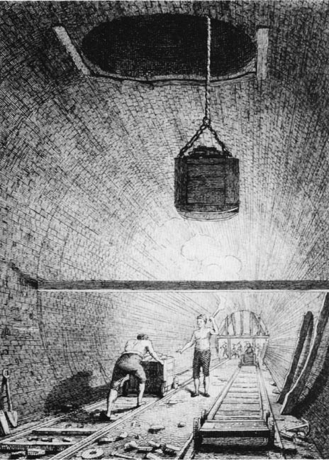
Tunnelling in the
canal-building era.
Blasting was resorted to when sinking a shaft and driving a tunnel
through rock. The technique was to hand-drill a shallow hole in the
rock formation, which was then dried out with oakum, packed with
black powder and plugged with clay. On lighting the fuse, the miners
clung, one above the other, to a winding rope and at a signal were
hauled some distance up the shaft where they remained until the
shots were fired. They were then lowered into the choking fumes to
remove the broken rock and debris, and then to repeat the process. Unsurprisingly, accidents occurred when the miners were not lifted
sufficiently high above the danger zone.
Tunnelling was hazardous in other ways. Many lives were lost due to
subterranean streams or quicksand deposits suddenly bursting
through, or the tunnel collapsing due to unstable rock; such
problems also meant extra time and cost to remedy. Leakage of water
into the workings was a continual problem and it was not unusual for
steam-driven pumps to be required to prevent flooding until the
tunnel’s interior could be lined, and sometimes even after that ―
the railway tunnels under the Severn (1885) and the Mersey (1886)
need to be pumped continually to prevent flooding.
Where flooding or quicksand proved a problem, or the formation of
the rock was unstable, the tunnel interior was lined with brick. Quicksand deposits were very difficult to tunnel through and
required heavy brick lining . . . .
“The manner in which the brickwork is laid is of great importance
. . . In a quicksand it has been found necessary to lay the lining
to the thickness of twenty-seven inches in the sides and top, and
eighteen inches in the inverts, Roman cement being used. [22]
This, however, is the greatest strength ever required; and, as the
nature of the ground will allow of it, this may be lessened to the
point where the material will stand by itself.”
Our Iron Roads, F. S.
Williams (1852)
Clay required similar treatment.
It was sometimes necessary to build
brick-lining into the sides of the shafts (following construction, some of
these
were then extended above ground to form small
towers, and used for ventilation). However, lining tunnels
with brickwork provided no protection against subsidence, which
could be very expensive to repair ― Brindley’s Harecastle Tunnel on the Trent
& Mersey Canal became one such casualty, the cost of repair being so
high that it was abandoned.
Few early canal tunnels had towpaths ― the Braunston and Blisworth
tunnels on the Grand Junction Canal being examples ― so boat horses were
led over
the ground above and the boatmen, possibly with paid help, would
‘leg’ the boat through by lying on their backs and pushing with their feet against the tunnel roof,
or lie on planks extending from the boat‘s sides (‘wings‘) and push
with their legs against the tunnel walls. Legging was a slow and arduous job, often taking two or three hours in
a long tunnel and causing considerable bottlenecks, especially if
the tunnel was too narrow for boats to pass. Such was the case
with Brindley’s Harecastle Tunnel ―
Telford’s later
tunnel, which was built to relieve the congestion, did have a
towing path. Some tunnels had ropes
or chains connected to the walls with which to pull boats through. Later, steam
or electric tugs were used before powered narrow boats
became common.
――――♦――――
LOCKS

|
A flight of locks at Foxton on the
‘old’ Grand Union Canal.
These locks have been built as a ‘staircase’ ― because the
incline is steep, the upper gate of one lock forms the lower gate of
the next. |

|
A narrow boat descending Foxton
Locks. This is a narrow (7ft) lock ― that in the photograph
below is broad (14ft 3ins).
The man turning the windlass is
raising the paddle to drain the lock chamber and lower the boat. |
A lock enables a boat to move between sections of canal at different
levels. In this respect it is identical in purpose to a step,
which performs the same function for a pedestrian ― moving from one
level to another through a small vertical distance. And as
steps are built into flights to permit higher inclines to be
negotiated, flights of locks perform the same function for a canal.
If rising ground that could not be bypassed was too
substantial for taking the canal through in a cutting, crossing over
it using flights of locks was generally considered a safer civil
engineering option than tunnelling, assuming that was possible.
However, the choice of which technique to use was not always clear-cut.
Flights of locks slowed traffic, while providing a sufficient water
supply to the summit could prove challenging. On the
Grand Junction Canal, the Chief
and Resident engineers couldn’t agree on whether to use flights of
locks or a tunnel to negotiate Blisworth Hill, so the canal company
engaged two eminent canal engineers to decide for them. Blisworth Tunnel
was the outcome, but it has proved exceedingly expensive to maintain
over the years. Further south at Cosgrove, the valley of the River Great
Ouse was originally crossed by two flights of four-locks.
These were
later replaced by a substantial embankment and an aqueduct, both of
which initially gave problems, subsidence in the embankment and structural
failure in the aqueduct. Thus, each approach for negotiating
inclines has its pros and cons.

|
A broad lock. The square
aperture in the lock gate is the ‘paddle hole’. The hole is
blocked by a sliding panel, the ‘paddle’. When shut, the lock
can be filled with water from the upper pound; when lifted (by the
‘paddle gear’ at the top of the lock gate), water can flow out to
the lock chamber to the lower pound. Note the ‘invert’, the
inverted arch of brickwork that forms the floor of the lock chamber.
This is built to resist upward and lateral pressures on the lock
chamber ― in effect, reinforcement. |
A lock consists of a chamber, usually built of brick and masonry, at each end of which
are fitted one, or a pair of
watertight gates. Traditionally, lock gates are built of oak or elm
and strengthened with ironwork. The size of lock chambers vary between
canals and even within the same canal. [23] However, many canal locks will accommodate a 72ft by 7ft narrow
boat, although narrow boats are now usually built to smaller
dimensions to give them a wider radius of operation. The
change in water level provided by a lock is termed its ‘rise’; that
for a single canal lock is usually in the range 7 to 12 feet.
A boat ascending from the lower to the higher level of a canal
passes into the empty lock chamber and the gates are closed behind
it to form a watertight seal. Water from the higher level of the
canal is then admitted to the chamber through valves, gradually
raising the water level in the chamber and with it the ascending
boat. When the water level in the lock chamber equals that in the
upper level of the canal ― the water pressure across the upper gates
then being equal ― the upper gates are opened and the boat passes
out of the lock chamber into the higher section of canal. The same
principle applies in reverse to a descending boat.
Using flights of locks to cross rising ground meant that the canal engineer had to solve the
problem of supplying the summit of the system with sufficient water
to carry the traffic, making due allowance for losses through leakage and
evaporation. Each time a boat crosses a canal summit, it uses two lockfulls of water, one on its ascent and one on its descent. This
quantity of water [24] flows down the canal and
has to be replaced if the summit is to remain adequately
flooded. Because water resources become less plentiful on higher
ground, a sufficient supply might require the construction of one or
more reservoirs to capture and store drainage water from the
surrounding area. If the reservoir(s)
was below the summit, steam pumping would be
necessary to raise the water to the summit level ― pumping water from
bore holes was another possibility to consider. Thus, if
either was required, the Chief Engineer needed to include its construction and operation in his costings (in periods of
drought, the cost of pumping could make a significant dent in the
canal company’s profits,
as will be seen). |

